• Join us and fill out the registration form with your INTERESTS, your CITY, STATE, COUNTRY, NO ZIP CODES! Your account is then manually checked and approved. Please follow these instructions by using City, State, Country in your location! Incomplete applications will be REJECTED. If you like what you see here, PLEASE SUBSCRIBE and support our web site! -- Harry

Generac Voltage Regulator Reverse Engineered...

jimgrease

Registered
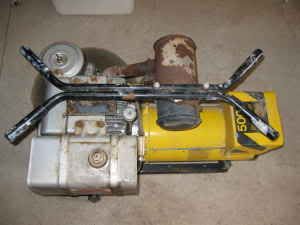
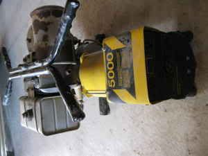
First post here at smokstak. I found this forum while doing research on my new to me but very old JC Penny 5000 watt generator. It's made by Generac and has a 10 HP Briggs side valve engine.

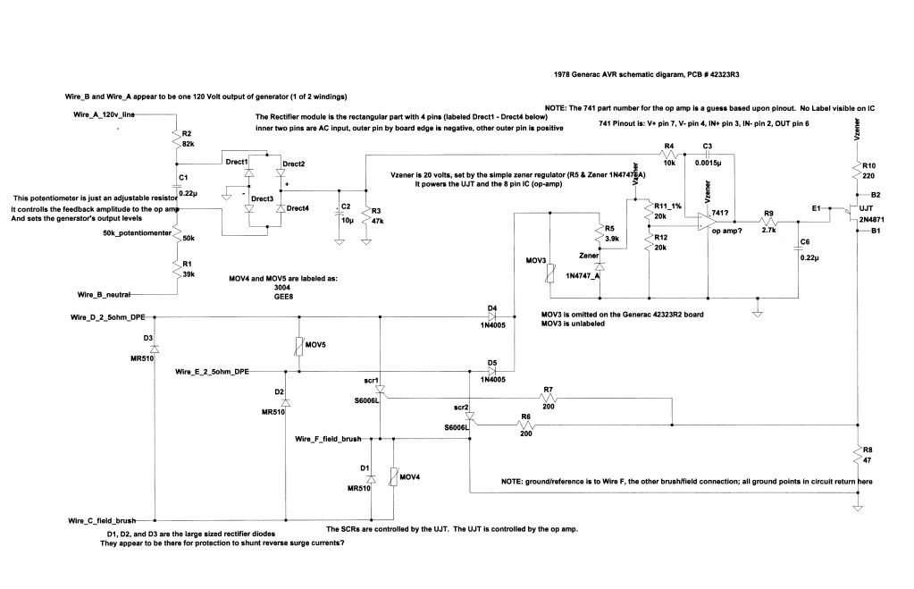
The voltage regulator board is identical to the MC-40 PCB posted here. There is only one part difference that I can tell, my board has an extra MOV.

Anyway, my generator runs but the voltage output was low. The 120 was at 36 volts, with the 220 at 72 V.

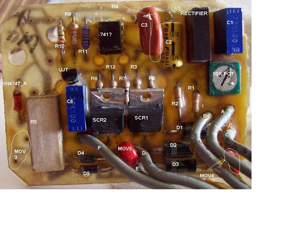
So I started the tear down and inspection process last weekend and finally got around to removing the potting from my PCB. Whew, what a mess:bonk:

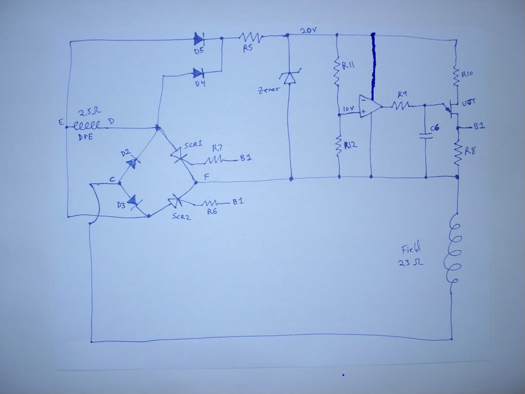
I'm about finished with the schematic drawings and I also know that at least one part on my PCB is fried. It happens to be the extra MOV, and it's shorted out depriving the Op-Amp IC of power.

If anyone is interested in my work, please reply and let me know that there is still interest in this old voltage regulator. I can post schematics and continue the discussion on this circuit.

I was looking around to see if anything newer could be easily built, but there are no complete schematics of a better circuit that I could find on the internet. If you know of any, please post a link. I'd like to compare this old op amp circuit to more modern designs.

Here is a photo of this old 1978 JC Penny generator:
jcpennyphoto1.jpg

jcpennyphoto2.jpg
 
Re: Voltage Regulator for MC-40 Generac

OK,

The schematics seem larger than I thought considering it's just a black and white jpg. So I apologize if this ends up wasting someone's bandwidth:O

First up is the schematic without extra comments:
schematic_42323R3.jpg


Next is the same schematic with some of my comments (which may not be right, always double check)
schematic_42323R3_comments.jpg


Last, we have the previous PCB photo with my part labels added:
regulatorpictureswithlabels.jpg


The PCB part number for my board is: 42323R3, and as I said before the only difference is an extra MOV on my board compared to the R2 version posted earlier.

My parts list:

Resistors (1/4 watt, 5% unless otherwise noted)
R1 39k
R2 82k
R3 47k
R4 10k
R5 3.9k 10% 5watt (power resistor)
R6 200
R7 200
R8 47
R9 2.7k
R10 220
R11 20k 1%
R12 20k

Capacitors (note that I originally thought two MOVs were caps, hence the out of sequence numbers):

C1 .22uf 100V
C2 10uf 16V polarized electrolytic (I'm going to replace with a tantalum)
C3 .0015u 100V
C6 .22uf 100V

Semiconductors

741 Op Amp 8 pin IC (guess based upon circuit config/pinout)
UJT 2N4871
SCR1/2 6006L
D1-D3 MR501
D5/D6 1N4005
20V Zener 1N4747_A (5%)
Rectifier SD?291 M7816 Motorola

Metal Oxide Varistors MOVs

MOV3 unknown, no label
MOV4/5 labeled: 3004 GEE8 (could not find data on these, I initially thought they were capacitors)


To trace out the schematic, I printed out in large size the previous two photos of the R2 PCB. Then I taped the printouts together back to back, and traced out the circuit. Finally I compared this to my own board, they are the same except for the R2 or R3 portion of the part number.


I think I'll start a new thread titled: "Open source voltage regulator circuit"

I'd like to compare this complete circuit to other designs and try to understand which configuration would yield the best regulator for a variety of generator loads. Please post if you have a suggestion for said circuit.

thanks
 
Ok, here's the problem...I've got a 1978 generac 4kw generator, mod # 6897-3, has a bad voltage regulator I believe....found the diagnostic and repair manual online, went thru the genny, I'm getting 150 volts at the terminals out of the generator....


Based upon what I've just learned about my R3 board (with many thanks for your photos of the R2 board) I suggest you look at that potentiometer closely for your over voltage running condition.

That potentiometer sets the feedback level that the op amp compares to the set reference. The reference is controlled by the zener, and I wouldn't suspect that to be off in voltage. However, if the pot drifted somehow, then the voltage output from the generator would change.

Have you tried adjusting the pot carefully while it's running? When I put my unit back together, I'm going to make that potentiometer accessible for running adjustments.

Be careful not to get shocked if you try to adjust while running :eek:

I'm fixing up an old 1978 Generac 5000 watt, JC Penny branded 10 HP Briggs generator. I've posted photos and a schematic of the old analog circuit board in the Voltage Regulator for MC-40 Generac thread

This is an old design, and I wonder how good it is compared to more modern voltage regulator circuits. So I decided to start this thread and ask the more knowledgeable folks here to comment on the best voltage regulator designs.

It would be great to have a collection of circuit schematics to compare with the one I just posted to the MC-40 thread. But that may not be possible unless lots of folks have done what I just did and removed the potting from their boards:bonk:

Not likely, I know. But I'll try asking anyway.

Let me also ask an easier question: Which generator over the years had the best reputation for starting difficult loads?

I heard that Homelite generators were good in this regard, but I admit that I don't have much actual experience to draw from when it comes to portable generators.

In my case, the worst two loads I'm likely to try running from the JC Penny gen is my shopsmith and my smaller arc welder. Don't know if my regulator board/10 HP mechanical governor Briggs will handle that:)

It should be fun to find out. The JC Penny 5000 watt generator lacks circuit protection. I suppose I should at least add a pair of fuses before trying a larger load.

Anyway, if you can tell me which mechanical governor generator had the best output regulation (or perhaps point out which had the worst output regulation); that would at least get me starting searching for voltage regulator schematics.

As far as I know today, the circuit schematic I just posted in the MC-40 thread is the only complete schematic for a generator voltage regulator on the net. That one can be scratch built by anyone looking to restore an older generator. Let me know if there are any others I've missed in my searching.

thanks,
Jim
 
Re: Open Source Voltage Regulator Circuit design

Post #11 was my attempt to start a new, generic discussion with the forum members regarding voltage regulator circuit boards. A topic that seems to interest at least some of the folks here based upon my previous searches on regulator circuits.

This head post was moved here and inserted as another reply??? The new thread I started appears to be missing? No explanation given for this move/change:(

I suppose I may have broken some forum rules somewhere, but it would have been nicer to have a quick explanation as to why the change?

With my post buried in another person's thread, I'm not sure we will have as good a discussion regarding regulator circuits as we could have had.

Jim
 
This is very good work. Thanks Jim... I am making it a Sticky....
 
Thanks for the sticky on this topic.

I do hope we can continue the discussion and perhaps design a more modern and useful "open source" regulator circuit.

I'm still working on my Generator. Life has taken it's usual twists and turns so that some of my projects have been put on the shelf. Or in this case, the corner of the garage, waiting for me to get back to it. Hopefully soon.

I still sneak peeks on SmokStak when I have a free moment. So if anyone has anything to say regarding voltage regulator circuits, please post.:wave:

Jim
 
So if anyone has anything to say regarding voltage regulator circuits, please post.:wave:

Jim


Yeah I got something to say.....I wish I had just 1/10 of your electronics knowledge!! Engines I'm good at. Electrical work I'm good at. But electronics.... I'm practically lost from the word 'go'. None the less, I'm following your work as it is very useful. Thank you.

Dave
 
I need to do something similar for a Coleman Powermate generator. The AVR boards are getting very scarce and expensive!

A simple regulator would rectify the DPE line to power the board. The AC output needs to be rectified and sent to a comparator to control a series transistor for the field winding. All relatively simple.

I built a similar circuit for the alternator regulator in my 914 Porsche. You can do anything with an op amp and handful of other parts.

Here’s my take on the circuit description. MY UJT and SCR theory are kind of weak. Both are relatively simple but I'll have to hit the books and brush up a bit.

It looks like the DPE coil is center tapped and referenced to ground. Diodes D4 and D5 form a full wave rectifier to create an unregulated DC power supply voltage. The Zener regulates the voltage for the op amp and UJT as well as the comparator reference voltage. 1N4747 is a 20V Zener. Oddly there is no capacitor across the Zener to smooth the regulated DC.

The generator AC output is sampled through R1, R2, and the 50k potentiometer. The potentiometer adjusts the voltage that is rectified and filtered by C2. R3 / C2 form a ½ second time constant to discharge the sample voltage in the case of heavy load causing output voltage drop. This allows the op amp to compensate and bring the voltage up again. Without R3 the sample voltage would remain high for an extended period even if the AC output voltage dropped considerably.

The op amp attempts to make the inverting and non-inverting inputs equal by controlling its output voltage. R11 and R12 form a voltage divider to create a fixed 10VDC reference at the non-inverting input. The DC voltage from the sample circuit is applied to the inverting input. The op amp adjusts its output to the UJT to increase or decrease the generator AC output voltage that is then fed back to the comparator.

C3 helps prevent oscillation at the op amp output.

R9 and C6 form a very short time constant at the input of the UJT. This helps prevent oscillation in the field circuit.

The UJT is essentially a variable resistor. It forms a voltage divider between 20VDC (Zener supply), R10 and R8. When the voltage at the junction of R6, R7, and R8 reaches the SCR threshold voltage they will switch on. SCR1 / D2 and SCR2 / D3 act as pairs to conduct through the field coil. The circuit can be redrawn to show DPE as an AC input, and the field coil connects to the full wave rectified DC output. This allows the field to conduct for up to the full AC cycle as determined by SCR1 and SCR2 turning on and off. Higher levels of SCR conducting will increase the field voltage and thus the AC output voltage.

MOV are essentially voltage variable resistors, almost like a zener diode. When the threshold voltage is reached the resistance will rapidly decrease. They are spike type protection devices, and under normal operation should not conduct. MOV5 limits the DPE output voltage and MOV3 limits the unregulated DC voltage applied to the Zener regulator.

D1 is reverse biased across the field coil. When field voltage is removed there will be a reverse voltage created that is discharged through this diode. Without the diode, there could be a very high DC voltage created that could potentially damage the MOV3 or MOV5. MOV4 is protection against spike voltages going to the field.
 
First I want to thank Jimgrease for all the work involved with removing encapsulation and drawing out the schematic. Warren I think you have it nailed except I don't believe the DPE winding is center tapped, if it were D2 and D3 would full field the rotor irregardless of the SCR conduction. I struggled with the circuit for a while until I figured the DPE ground reference to the rest of the circuit was through the field. I too had to brush up on UJT theory. Lloyd H
 

Attachments

  • schematic_42323R3_comments.jpg
    schematic_42323R3_comments.jpg
    36.2 KB · Views: 2,110
Last edited:
Agreed on the DPE winding. It's a single wiring with no ground reference. I went through the diagram again and redrew the SCRs and diodes. The DPE return is through diodes D2 and D3 forming a full wave rectifier to ground through the coil.

Still doesn't look right. I'm confused with the polarity of the SCRs, D2, and D3. If the position of the diodes and SCRs were changed and all polarities reversed, D4 and D5 would create a full wave bridge rectifier with D2 and D3 connecting to ground at wire F.
 
My take on the circuit:

D1 is used as a snubber diode for the Field. D2, D3, SCR1, and SCR2 form a full wave bridge rectifier with the DPE winding as the source and the field as the load. The bridge can be controlled, turned on or off, by the voltage on the gates of SCR1 and SCR2. I think this is called a thyristor regulator, since it uses SCR's instead of a transistor running in the linear mode. The advantage is it does not generate a lot of heat since the SCR's are either on or off. You can see this kind of circuit in the "Regulator/Rectifier" modules used to charge the battery on a lot of small engine equipment like motorcycles or snowmobiles.

One of the 120 volt output windings is sampled by a divider string consisting of R1, R2, a 50K pot, and C1. The capacitive reactance of C1 is approximately 12,000 ohms at 60 Hz, so the circuit is dividing the input voltage between 6.5% and 9%, depending on the setting of the pot. That sample is rectified by a full wave bridge, filtered by C2/R3, and sent to an op amp set up as a comparator. The 10 Volt reference voltage to the comparator is set by R11 and R12. If the sample voltage is below 10 Volts, the output of the comparator is V Zener, or 20 volts. This turns on the UJT, which turns on the SCR's, allowing current to flow from the DPE winding to the field. When the output voltage comes up to the set point, the sample voltage rises above the reference voltage, and the output of the comparator goes to 0, shutting down the UJT and the SCR's.

I think this circuit could be adapted to a lot of small generators that use a DPE winding and voltage regulator. Due to liability, you could not commercially repair any generators with this, but for your own stuff it could work when a replacement part is NLA or just priced out of sight. As soon as one falls into my hands, I am going to give it a try.

I think Onan used this type of circuit in a lot of their earlier generators. It might be worth it to ask a dealer if he has any defective regulators he would be willing to give me. I would like to reverse engineer one or two.
 
Gentlemen, thank you for the feedback.

It would not surprise me if there is a mistake in my schematic, its always good to have these things double checked.

Also, I'm glad we are focusing on the lower half of the circuit, from the UJT to the SCRs. Since this is my first generator rebuild, that is where the confusion is for me too:)

Let me also say: don't assume anything I labeled is correct. You might try erasing my wiring labels to see if the connections then make more sense.

The photos of the Printed Circuit Board (both sides) are in the other thread if you want to try tracing some connections visually.

My schematics were drawn in LinearTech's free switcher cad software, and I did attempt to simulate this circuit last year. I'll dig up that project and start studying this again.

To be continued.......................
 
I took a moment this afternoon to review my notes on this circuit. I haven't found any mistakes so far, but I did redraw the lower half of the circuit based upon the descriptions posted here.

Lets see if this helps:
01310001.jpg


I did not include the following in the above hand drawn schematic:
- the feedback circuit to the negative input of the Op-Amp.
- MOVs
- protection diode D1

There are two bridge rectifiers shown in this portion of the circuit (there are 3 total in the entire regulator). Diodes D2 and D3 are shared between the two bridges.

All the current in this portion of the regulator returns through the field winding.

So I would say that as the voltage changes across the field when operating normally, the voltage across R5 also changes. It's weird, but wire F is the reference point for most of the circuit elements.

This gen set of mine appears to have thermal switches in the output windings. If the switch disconnects the load, and if the regulator is still being powered; then once the load is reconnected the voltage will be at maximum. There is a warning to disconnect anything attached to the generator output if the thermal cutoffs are activated. I was exploring ideas on how to prevent this overshoot for instances when the feedback signal drops to 0.

The easiest thing I could think of would be to add a relay that switches in the Zener only when there is power on the feedback circuit. Any thoughts?

Of course I need to get back to this project and start testing things out. Unfortunately, I'm still dealing with too many other more pressing chores at this time.

Feel free to take it and run with it:D
 
scan001.jpg


This diagram would provide continuous DC to the zener diode. The SCRs would turn on as needed to power the field. Thoughts?

In your generator, when the thermal switches open the quickest way to disable the regulator is to use a transistor either in series with R5, in parallel with the zener, or across R12 at the op amp. In either case the UJT can be disabled and the output to the field turned off. Mechanical relays are slow and bulky.
 
Warren, what you drew is how I thought the circuit was setup when I started this. I don't yet understand the electrical trade offs being made between a parallel connected field (which you drew) and a series connected field (which is in the old Generac regulator board).

I suppose it could have something to do with noise and spikes in the system. Would a series connected field be less of a spike problem to the parts in the zener regulated portion of this circuit?

Another theory is that Generac did this just to confuse those who try to reverse engineer the circuit :)

I don't know. I was hoping someone more knowledgeable would offer an explanation.

I mentioned the relay earlier because I was concerned about the control signal return path. The relay provides the best isolation between control signal and switched outputs; and I thought it would be safest for this application.

Another idea would be to add a triac to control the AC going to the Zener regulator using a completely separate bridge rectifier. That triac would then need to be controlled by the feedback network, possibly by using the DC value at C2/R3, but again, what about the return path for the triac control signal? I need to think about that idea some more and understand better what is actually happening in this Generac regulator circuit. Triacs and SCRs are not my main area of study.:D

I did look up UJTs in my old Industrial Electronics textbook. Here is the relevant page:
02010001.jpg

You'll notice that this UJT oscillator circuit is just like the configuration in the regulator circuit. When the Op-Amp provides enough voltage, I think the UJT starts providing triggering spikes to the SCRs. Feedback capacitor C3 must trade off regulator response time with output stability; giving the system the necessary damping. My limited simulations in Switcher CAD showed these oscillating spikes going to the SCRs.

Regarding the DC power for the Zener regulator, resistor R5 is rated for 5 watts. I think that implies about 90 Volts average DC across R5 if we assume the worst case power dissipation is 2 watts. This could explain the lack of a bypass capacitor on the Zener output; it just isn't needed here. There appears to be more than enough head room to operate the Zener regulator and I don't think this circuit would work well unless the 10 Volts at the voltage divider R11/R12 was constant.

Which brings me to a question: what is a typical DPE output level? This old 70s Generac seems to me to have a very high DPE output voltage (and dangerous), but I'm not familiar enough with backup generator design to know. How does this compare to more modern gensets? Perhaps my labeling this winding as 'DPE' is incorrect?

If I get any free time I'll attempt to breadboard the Op-Amp and UJT portions of this circuit and try to observe the SCR triggering spikes. I'll also try substituting a 741 Op-Amp for my unlabeled original to see if the circuit still behaves the same way.
 
I measured the DPE voltage while repairing / testing my 7000EXL. It gets surprisingly high!
http://members.rennlist.org/warren/7000exl.html

I'm expecting a new AVR board for a Coleman Powermate generator to arrive in about a week. Before it gets installed I'll try to trace it out. It uses five wires from the alternator plus another two for the brushes. Could be interesting to see what approach is taken.

It seems very strange that the diodes would be connected as in the original diagram. Unless the field current is flowing there will be no zener voltage. And with no zener voltage the SCRs can't turn on the field. Somewhat of a Catch-22.

Even with 90V applied to R5, the rectified DC will still go to zero at each half cycle. That's where a capacitor across the zener would really help.

For the IC, check pinouts of comparators such as the LM201 or LM301. The 741 op amp can be used as a comparator, but its output will not snap to each rail in the same manner.
 
quote Warren "It seems very strange that the diodes would be connected as in the original diagram. Unless the field current is flowing there will be no zener voltage. And with no zener voltage the SCRs can't turn on the field. Somewhat of a Catch-22." I struggled (a lot) with that as well but finally got it. D2 and D3 alternately conduct through the field coil to ground, through the zener diode and R5 then alternately through D4 and D5. I believe the zener current flashes the field for dependable startup. I too would be more comfortable with this theory if there were a filter cap across the zener. D1 will limit the inductive effect of the field coil to its forward bias of about a half volt, would that have an effect? Could the zener voltage vary from D1 forward bias to 20 Volts each half cycle to time the UJT firing? Inquiring minds want to know. Lloyd H
 
Let me offer another hand drawn partial schematic to help others follow along and to further discuss this Zener regulator/missing filter cap portion of the circuit:
02020001.jpg

I left off the SCRs this time, but D1 is in the diagram. The missing filter cap is something I would have included in the design had I been building this circuit, and it is indeed curious that it's not there.

If the DPE peak voltage is high, and I think it is given my estimate of 90 Volts RMS based upon the power rating of R5, then the amount of time that the DPE waveform spends below 20 volts is very short. So the question is: does this short time below 20 volts matter in this circuit? Since Generac didn't include the filter cap, I would guess that not installing it does not affect the performance of the regulator. But I also want to know :)

I suppose I should add another experiment to perform with my spare parts. I think I can simulate the DPE with a transformer from my junk bin. Then I can hook up some other parts to simulate this section of the circuit and probe for a stable voltage across the Zener. I unfortunately broke my Zener when removing my potting compound and have yet to replace it, but I'll bet I have another lower value Zener suitable for this experiment in my junk bin.

The Op-Amp guess was based upon the circuit configuration and the pinout of the 8 pin IC. Op-Amps have power supplied on pin 7, which is where the 20 Volts is connected to the IC. The standard 311 comparator has power on pin 8 if I recall correctly. Also, the comparator is open-collector output and needs a passive pullup, which wouldn't work in this circuit. I'm pretty sure we are dealing with an Op-Amp and not a standard comparator. Any of the 40 Volt rated Op-Amps should work considering the frequencies we have in a backup generator. I think the 741 will work fine, but the 301 and 201 Op-Amps would probably also work. Electrically, they all appear to have very similar characteristics.

Won't know for sure until after some testing. So, I'll just have to find some bench time:D
 
If you look at the circuit board, there is an unused space available for a filter capacitor for the zener voltage. The capacitor negative lead would go to a hole just above and to the left of R5, the 3900 ohm 5W resistor. The positive lead would go to a hole straight above near the edge of the circuit board.

Onan used a circuit very similar to this in their YD series of generators. The service manual number is 900-0184. You can get it here:

http://www.cumminsonan.com/www/pdf/manuals/900-0184.pdf

Look at pages 19 and 33 for schematics of two voltage regulators. The circuits are very similar, with the Onan's not skimping on components. The one on page 33 has an option to allow the voltage to roll off with frequency by placing a jumper to select a filter network.

One would ASSUME the DPE winding produces a sine wave in phase with the output voltage, but this may not be the case. I have a couple of generators using the "harmonic winding" method of regulation with no voltage regulator, and it is not a sine wave produced by that winding, more like a voltage spike. I realize we are talking about different methods here, but it would be interesting to use a scope to check the output of the DPE winding for waveform and phase relationship.
 
One would ASSUME the DPE winding produces a sine wave in phase with the output voltage, but this may not be the case.

I would assume that the Displaced Phase Excitation(DPE) winding produces a sine wave at some angle to the output voltage other than 0 or 180 degrees.
Keep up the good work.
Jack Hottel
 
Back
Top